Automated Exterior Lighting Control Using Texecom Premier 832 Security System
With one of the highest crimes rates in the world, home security is a fundamental consideration in South Africa. This usually involves creating multiple security layers, starting with boundary security using physical boundary barriers, exterior threat detection using devices such as passive infrared detectors and/or cameras, eventually culminating in building entrance detection and protection as well as interior detection.
Many of these components are usually integrated together as sensory inputs into a single security controller, that detects breaches of areas or zones that in turn, can be used to initiate actions and operate outputs based on the zone or zones violated, and the state of the alarm controller (i.e. is it in an away or stay armed state, or disarmed). This may include, audible or inaudible alarms and/or toggling radio transmissions to security companies for example, that will send armed response personnel to investigate the cause of the alarm.
In the case of unwanted visitors, particularly at night, early discrete perimeter detection in conjunction with come resulting automated actions that do not require any homeowner intervention due to them not being at home or asleep, are often sufficient to make said visitors sufficiently uncomfortable to leave the vicinity. At least that has been my own personal experience.
An example of this would include exterior infrared point-to-point beams or passive-type detectors that if violated or triggered when armed at night, would cause outdoor lights to turn on automatically after a detection delay, thus hopefully surprising the would-be absolute discount shopper, as they have no way of knowing if the lights are automated or not, likely assuming the latter since light automation in this way is not commonly implemented.
The Scenario
It was thus that I recently wished to implement something to this effect on a home that already had a number of MS-12 Takex dual-zone exterior infrared passives installed strategically around the exterior of the building. The detectors are in turned linked to the home's security controller, a Texecom Premier 832 device, as a separately logical group or partition. Usually the external passives are only armed at night when the owner puts the alarm into "stay" mode or when going away on holiday.
Fortunately, I had already had the displeasure of having to configure the Texecom system before, and I own the USB programming cable for the panel as required by the WinTex programming software since my own home uses the same panel. The Premier 832 is, or at least was, a reasonably popular alarm system controller in South Africa, amongst a raft of other brands. The system documentation is good, but the WinTex software is not great. I surmise most of the resulting frustrations in setting up the controller relate to the fact that multiple versions of the device firmware appear to be available in the WinTex software and you need to select the correct version of firmware that matches your controller. This is not as bad as it sounds as the software is clearly able to detect the version itself so if you select a version that is incorrect, it promptly informs you. Thereafter, it seems the software assumes that all the configuration options it presents are available in all firmware versions. This appears not to be the case and can lead to much hair pulling when adjusting many of settings results in absolutely nothing, despite them appearing very straight forward and logical, such as if an alarm occurs, toggle a specific output. In many cases, the output simply does not toggle in the alarm state, despite my pouring over the documentation to verify said output should in fact toggle.
Also most importantly, I had the engineering/configuration user password for the alarm system, thus I am able to make configuration changes as required. Without the password, you cannot connect to the panel. Unfortunately, these systems are often password protected by the installer, with some strange hope that you would be locked into using their services forever more. However, this password can be reset to the default but it does mean resetting the entire alarm panel and thus losing the configuration and having to set it up from scratch, which while not impossible, won't be fun if you haven't done it before or at least have an understanding of the way these security controllers generally work. The programming manual for the system that describes all the settings in more details can usually be found online through a Google search - getting documentation directly from Texecom can be a bit painful as you need to register an account simply to be able to download a user manual.
My intention was to integrate six 30W LED floodlights with the alarm system controller, such that they turn on automatically at night as described, as well as also be able to turn the lights on and off manually on demand, using something akin to a light switch.
System Components and Implementation
The concept I had in mind, required a few components, in addition to the lights and alarm controller, notably something to act as an interface and switch the lights on or off, since the alarm system works on 12V DC, and the lights are 230V AC. Also, I knew from previous experience that I would need something to keep the lights turned on for a period of time after the alarm controller had signaled that one or more of the exterior PIRs had detected motion. All the "additional" logic required to implement the system I've lumped into the DC/AC Control logic block in the diagram below, which is I will expand on. As an overview, the system components look like this:
 |
General system components for controlling the LED lights. The red lines indicate AC power. |
In order to implement the automated lights, I first need to add some LED lights. Since the lights are the end goal, I'm going to describe the components starting with the LED lights and going backwards. The six floodlights were installed at strategic positions around the house to ensure the entire perimeter of the building was lit at night. These lights all needed to be supplied by 230V switched on and off by the alarm system but the source of the power would be obtained by connecting into an existing 230V lights circuit by making a single connection into one of the existing lights circuit cables - which end up being easier said than done.
 |
Conduit Picasso. If you can imagine a plate of multi-coloured spaghetti, you will know exactly what the inside of the junction boxes look like. |
For reasons that only the installing electrical could justify to himself, all the house electrics are wired with standard, single core, single insulation layer house wire. Due to the use of this type of cable rather than double insulated, twin and earth cable which could be run directly in the roof, all the wiring runs in conduits and the cables all congregate into a couple of large junction boxes. The result is a veritable conduit maze and junction box cable vomit, with no labelling of any kind, and barely any space to stand in the roof without inadvertently crushing a conduit. But this type of idiocy, disregard of maintenance ramifications and lack of pride in ones work is quite normal in South Africa.
I was able to identify the lights cabling by turning off all the other house circuits and using my multimeter's AC proximity detection function to identify and trace what cables were still live. Having made a joint in the junction box, I ran a new cable to a day-night switch I mounted externally under the roof. This switch ensures that the AC power to the LED lights is only available after dark since it would be fairly pointless and an obvious indication of automation of the lights turned on during the day. The AC cable then runs back to a new junction box that contains an AC 16A relay circuit a small off-the-shelf item with terminal blocks for easy wiring, reverse EMF diodes etc. all integrated onto a small circuit board.
 |
| The AC relay module allows a 12V DC signal from the alarm system to switch the larger 230V AC power to the LED lights. |
The 230V live cable from the day-night switch is wired into the COM (common) terminal of the relay. The output of the relay, N/O (normally open, meaning the default state is open or not connected), is joined to all six LED lights in the junction box. Thus, all we need to do is correctly switch the relay on and off at the right time to get the lights to do what we want.
 |
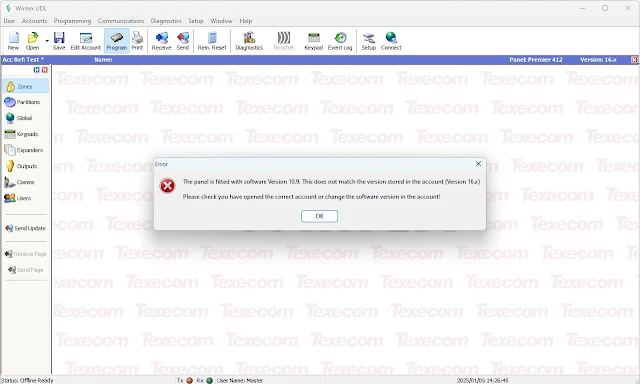
| A 433Mhz remote receiver and timer module power the AC relay coil in parallel, meaning either input can switch the lights on. The relay can be switched by applying 12V DC to the coil input. Here, I decided to add two inputs in parallel. First, we have the output of a timer module. This is a general purpose, off-the-shelf timer circuit that can be configured with a few options such as various operating modes, what type of signal starts the timer, and if the timer is reset if the input signal re-occurs while the timer is counting down. I used the timer in "timed relay output" mode. In this mode, the timer will keep the relay powered for a duration of choice (5 minutes in this case) and thus the lights on for the duration of the timer, despite what the Texecom alarm input signal does. I also configured it to reset the timer in case the alarm controller raises further alarms, thus the lights could stay on for as long as motion is detected, as long as 5 minutes does not elapse. The timer was also configured with a negative edge trigger which is what the Texecom alarm supplies (i.e. the Texecom alarm output goes from 12V to 0V when a trigger occurs and thus the signal edge falls or is negative). In conjunction with the timer, I also added a single output 433Mhz remote receiver to act as a latched relay input. The way this works is once the remotes have been programmed into the receiver, when the remote button is pressed, the receiver activates an internal relay. Since I put the receiver into latched mode, it will alternate between on and off every time the remote button is pressed. This allows the lights to be manually controlled if desired at any time, even when the alarm controller is not armed, and is therefore provides operation like a wireless light switch. If either the alarm controller or the remote receiver is "on", the lights will be on - both must be off for the lights to be off. Controller Alarm Flow Thus, the only outstanding system input is the "alarm" signal from the Texecom controller. To get the desired results, we want a 12V signal from the controller that occurs when motion is detected by the external PIR sensors. In my case, I wanted the signal only to occur after a delay, so that any correlation between a PIR sensor detecting something and the lights being activated is less obvious. In this particular setup, this is achieved by having all the external PIR sensors configured in a single group, or Texecom system partition, that is, they are logically separate from all the internal sensors, which are in another partition. This allows the external sensors to have some different behaviour attributes assigned to them. For example, I didn't want the external sensors to activate the alarm siren if toggled when the owner was at home and the alarm was in "stay" mode, since in my experience, the "shock" factor to the home owner of the alarm going off in the middle of the night is rarely useful. Instead, if triggered, the external sensors cause the alarm keypads in the bedrooms to omit a more subtle but still very audible pre-alarm tone for a predefined duration, which forms part of the lights "pre-trigger" delay. The sequence of events if the external sensors are triggered During this pre-trigger delay, only the panel tone sounds, which is usually sufficient to wake the home owner if the alarm is stay armed. Once the pre-trigger delay expires, the alarm controller activates a specific output signal which is what is wired into the timer module. I specifically disabled the alarm siren output in the case of an external detection and if the alarm has been stay armed, thus the alarm siren does not sound - only the outdoor LED lights turn on. The one notable caveat of this approach is that for some reason the Texecom alarm panel does not indicate which zone, or area, has been violated during this delay - the area is only shown on the panel display once the delay has expired. Controller Configuration To configure the Texecom alarm, you will need to install the WinTex software on a laptop. You can obtain WinTex from Texecom, but you have to register as a user which is an annoyance and it can often be found elsewhere through some searching. The latest available version at the time of writing was version 8.2 The Premier 832 installation manual can also be useful to describe the various settings and options. Main components inside the alarm controller housing To use the Wintex software, you will need a USB programming cable. If required, the WinTex software includes the drivers for the cable in the installation path (default c:\program files (x86)\Texecom\WinTex) under the USB-Com folder. Once connected to a laptop, you should see an additional COM port in Windows Device Manager. If this is the only serial port connected to the laptop, it will show up as the only selectable option in WinText. In the case of the Premier 832, connect the other end of the cable with the keyed white 5-pin Molex connector to the port labelled COM 2 on the alarm panel board (the second white connector from the top right). USB-Com cable connection for laptop, highlighted in red. On starting Wintex for the first time, you will need to create an Account by clicking on the New icon on the left in the icon bar. |
 |
| The USB-Com COM port in this case is COM7. |
 |
| Don't forget to fetch the current panel programming data otherwise you will overwrite the settings with a blank/default configuration if you do a Send. |
 |
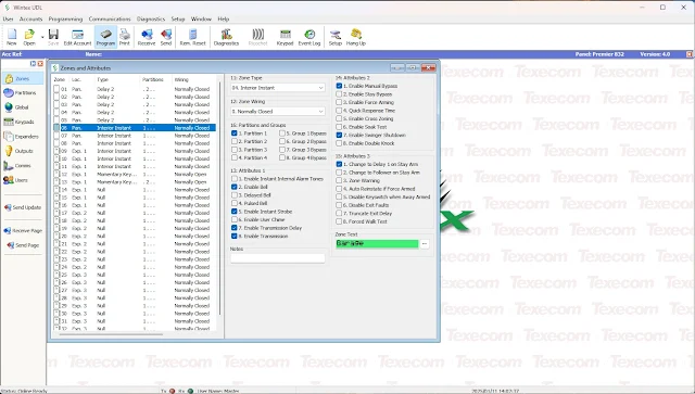
| Note Zones 1-6 are specified as part of Partition 2 and do not have a bell or strobe alarm attribute set. |
 |
| The away arm Delay 2 was set to 15 seconds and the stay arm Delay is 30 seconds before toggling the exterior lights. |
 |
| Apply changes to the alarm controller by selecting 'Send Panel Programming Data' from the Send button menu. |
 |
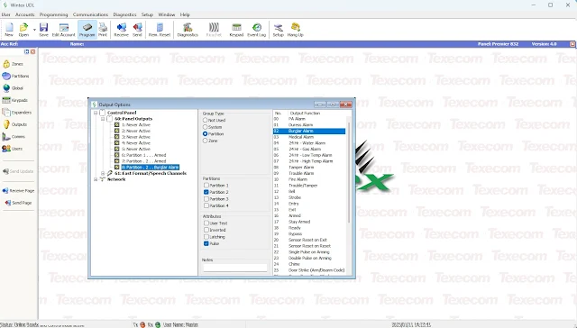
| The Onboard Comms status shows when the internal Burglar Alarm signal is triggered after the requisite Entry Delay timeout when an outdoor sensor has detected motion. |


Comments
Post a Comment